|
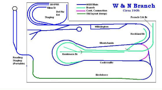
The Operating Scheme
The W&N will operate with each crew making one or more round trips from the terminal at either Reading or Wilmington,
to the other end and return with another train. Each crew will get their engine, take it to the train, make the run, yard
their train, get their caboose, put it on the outbound train and then return to the origin. Between round trips they will
have to get coal and at least once on every round trip will have to stop and take water.
The original operating sessions were 3 hours long using a 4:1 fast clock, for a 12 hour slice of the day.
I have had 7 sessions with this operating pattern. Each session operated the same set of trains.
I am revising the operations to have a 8 hour slice with a 3:1 fast clock for a 2 hour and 40 minute session.
I have 3 different "shifts" of trains planned, so each session will be slightly different than the previous one.
The positions I have used so far were:
Wilmington Yardmaster/Switcher
Wilmington City Job
2 road crews for 1-2 psgr trains, 3-4 frt trains and a local each
I have not needed a dispatcher since I have required relatively few orders. Most sessions require no orders
and the most I have issued in any given session was 3.
In future sessions I will add a Coatesville switcher. Once the French Creek Branch is in service, I can add
a 3rd road crew that will run the French Creek local and several transfer jobs.
Reading Portable Staging Yard
In order to accomplish the operating plan I needed some staging at the north end of the layout. Birdsboro did not
have the capacity to stage and operate fluidly, so I designed portable staging to fit in the hallway outside the railroad
room that represents Reading, PA. It is very lightweight construction with 1/4 in plywood with 1/2 x 3/4 pine strips
glued to the edges and as reinforcing. Its a bit noisy but easy to move.
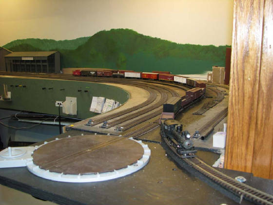
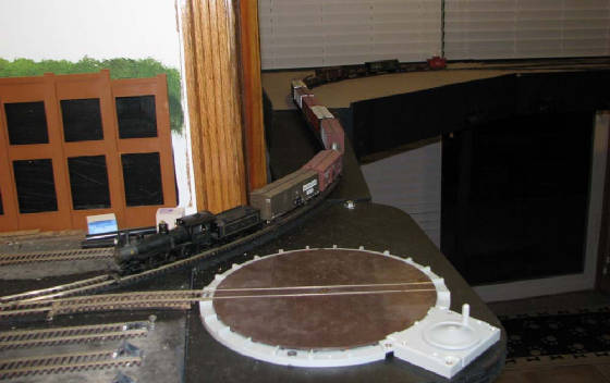
The first train runns through Birdsboro and onto the new connection to staging.
The train pulls into a staging track, and the engine cuts off to run onto the manual turntable. If the crew turns
at Reading, they will run back to the south end of the yard, pick up their caboose and bring it back to the turntable, which
is long enough for one engine and a caboose.
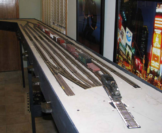
The yard has 7 tracks on a 16" wide deck. That allows tracks 1 and 7 to be running tracks. Tracks 2 through
5 are the primary staging tracks, three of them are 12 cars long and one is 15 cars long. There is a run around built
into tracks 6 and 7. That allows a short train to be staged in 7 tail (stub ended) or between the switches in 6.
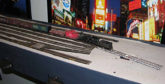
In addition, on the south end, there will be two coach yard tracks on the back side and two or three engine tie up tracks
on the front side (on the corner module). On the north end, next to the turntable off track 1 is a short stub that can
hold two cabooses.
In the future I will build a "docking area" opposite the yard on the turntable end to allow cassette staging to be used
for both storage between sessions and to allow more trains to be originated from Reading if the operations require it.
Having turned the engine and caboose the crew puts its caboose on the outbound train (which in this test run is the inbound
train). Then the engine backs onto the turntable, which is lined for a clear track, and runs to the south end of the
yard to get back on its train.
The southbound train departs Reading onto the permanent layout. The extension intrudes into the door way slightly,
enough to get the tracks through but not enough to impede movement. The turntable is there to allow operation (turning
steam engines) without the staging yard in place.
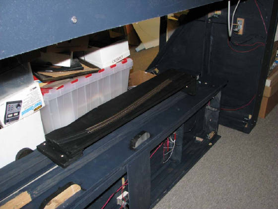
Twenty minutes later the whole staging yard is broken down into 4 pieces (two 16" by 66" yard modules, a 36"x36" corner
module and a 8"x30" connector) and stored under the layout. Why such an odd length of 66' for the modules? My
layout is built on 72" grids so the layout legs are on nominal 72" centers. By making the modules 66" I knew I could
fit them between the layout legs for storage.
|