While building my previous layout I decided that the switch throws would be manual, since the switches on the prototype
I was model were hand throw switches. Even though I was modeling in HO, I decided to use Caboose Hobbies N-scale switch stands
in order to minimize the size of the switch stands. My switches were hand laid and the N-scale stands had sufficient throw
to operate them. The problem was that I needed electrical contacts to control the polarity of the frog when the switch was
thrown.
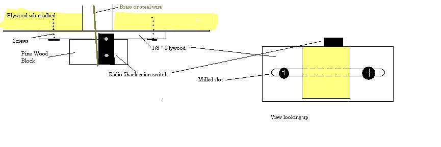
The first couple attempts used Radio Shack 252-176 microswitches screwed to the bottom of the roadbed. These attempts
were judged unsuccessful since there was no way to adjust the microswitches efficiently. I decided I needed a bracket to hold
the microswitch vertically so the movement of the points would throw the switch. The bracket had to allow some horizontal
movement to adjust the microswitch to the movement of the points. The lever arm had to be extended to mate with the points.
Given these requirements, I designed the bracket shown in Fig. 1.
The base is a piece of 1/8 inch thick Luan plywood cut into 1 ½ by 2 ½ inch rectangles. A table or radial arm saw will
allow a large number of these bases to be cut at once. A 1/8 inch width slot was routed down the middle of the base. To do
this quickly, I made a jig using a scrap piece of ½ inch plywood and tacked pieces of 1/8 inch plywood down to hold the base
blanks with minimal movement. Scraps of 1x2 wood were nailed to the plywood to form stops to limit and guide the movement
of my router. Using this jig, routing the base slots was quick work.
Small blocks of ¾ inch thick white pine were cut 1 inch wide by 2 ½ inches long. Make sure the end grain of the wood is
not on the 1 inch wide end. Once again, a radial arm saw or table saw helps make this cutting go quicker and more accurately.
Clamp and glue the wood blocks to the bases making sure the 1 inch wide side is flush with one of the long sides of the bases.
In most cases the wood block can be centered on the base, but in certain circumstances it may be necessary to mount the block
on one end of the base to offset the mounting.
The microswitch has a flat metal lever arm that actuates the microswitch. I was not very successful soldering an extension
to that metal lever arm. To overcome that I cut a ¼ inch by ½ inch piece of .005 inch brass sheet and wrapped it around the
lever arm near the end. A piece of piano wire or brass rod about 2 inches long was soldered to the brass sheet. The microswitch
is then screwed to the wood block on the bracket. The rod should be as close to vertical as possible, which means the microswitch,
will be cocked at a slight angle.
The microswitch has three contacts on it, the one closest to the hinge is the common, and it must be connected to the frog.
The other two are the normally open and normally closed contacts. They are connected to the stock rails of the switch. Depending
on the orientation of the microswitch to the track switch, which one goes to which stock rail will vary. It is best if all
the microswitches are mounted on the blocks in the same orientation. It is handy to use different color wire to the common,
normally open and normally closed contacts and then keep that color-coding consistent on all microswitches. The wires can
be attached to the microswitch before installation on the layout or with the microswitch in place under the layout, depending
on your flexibility and comfort level soldering upside down in tight spaces. . If additional contacts are required for signals
or other purposes, the microswitches can be ganged and the brass sheet can be made larger, connecting the two lever arms
Before the switch is installed, the area where the throwbar is going to be must be located. I glued paper switch templates
to the roadbed to locate the throwbar. A slot must be cut or hole drilled under the throwbars to allow the microswitch rod
to pass through the roadbed. I drilled a 3/8 or ½ in hole through the roadbed in the track centerline at the throwbar. The
ties were glued to the template, over the hole. The switch was laid and a small hole was drilled in the center of the throwbar.
Connect the switch stand to the throwbar and adjust it to throw the switch properly.
The microswitch is installed by threading the microswitch rod up through the hole in the roadbed and through the hole in
the throwbar. The base is positioned so the slot is roughly perpendicular to the track centerline. The bracket is gently slid
to the side until the microswitch just throws. The base is screwed to the roadbed through the slots with pan head screws or
wood screws with a small washer. The track switch is lined for the opposite route and the bracket is slid back and forth gently
until the microswitch just throws. With practice it becomes easy to position the brackets so the adjustment takes just a couple
throws. Tighten the mounting screws. Connect the microswitch contacts to the track. The rod can be trimmed back with flush
cutting pliers or a cutoff wheel in a motor tool so it doesnt foul coupler trip pins or locomotive pilots.
My micro switches with this style bracket survived three moves and several years in storage with no failures. Several of
the ground throws failed, but not the microswitches. Hopefully this system will provide your railroad with years of reliable
service also.